Started January 10, 2007
The electrical system is one place where builders vary quite a bit. There are so many choices to be made. Do you want fuses or circuit breakers? Do you want traditional switches or the full blown system like the EXP-2 bus? Do you want a key switch for your magnetos and starter or two toggle switches with a push button starter? In fact, do you even want an electrical system at all? The first prototype had no electrical system and Bob just hand propped it to start.
I have elected to go with the Bob Nuckoll's system. Bob is an electrical engineer with ton of experience in aircraft electrical systems. I highly recommend you get the Aeroelectric Connection by Bob Nuckolls. In this section, I'll be referring you to a lot of links to articles in the Aeroelectric connection, on how I did my electrical system. Its all already written so I figure "why re-invent the wheel?" Click on each link as you come to it and you will see it come together.
You can get a real good start on all of the main rules that I used for creating an excellent, reliable electrical system by reading this article. I also recommend that you read all of Bob's online articles (he calls them comic books) available on his website here.
I'm going to share what I am installing in my airplane for an electrical system but again, this not the be-all to end-all systems. You choose what you want to install in your airplane and do the research ahead of time to get it right. If you want to copy any or all of this be my guest. I feel its a great system for a simple day/night VFR airplane. If this were going to be an IFR airplane, I would probably add a second alternator and possibly a second battery to the system. To see my instrument panel layout click here and then come back to this page.
I'll be using a fuse block system with a simple toggle switches to control everything. I have decided to use the Key switch with starter function for the magnetos.
The fuse blocks will act as the electrical buses where everything is powered from. I'll cover that in a minute.
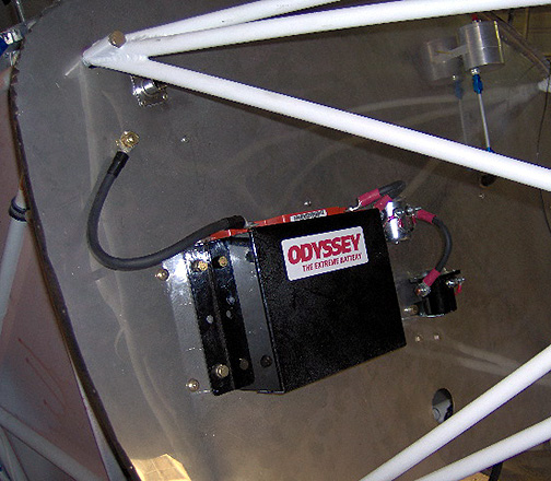
Lets start with the Battery and work our way back. Since I have the lighter O-360 engine with a fixed pitch prop, I'll need some more weight forward of the CG (center of gravity) for Weight & Balance reasons, so I'll mount my battery out on the firewall. Builders with the heavier O-470 and O-540 engines, especially those with constant speed props, might need to mount the battery further aft.
As for the battery, my research has turned up a lot of good things about
the Odyssey 680 Drycell Battery:
For the large terminals like the ones on the battery, starter and Alternator "B" lead, I used the techniques shown in this article to make the wires.
One of the places that I think a lot builders neglect is the firewall pass-through for wires and tubes and such. You must have a safe, fire and smoke proof way to get wires from the engine side, to the cabin side of the firewall. On many of the homebuilt airplanes I've looked at, all I see is a plain rubber grommet where the wires or hoses come through the firewall. Engine compartment fires are rare, but do happen on occasion. The thought of being at 3,000 feet and having smoke and flames entering the cockpit scares me. So I'm doing all that I can to buy myself some time to get safely on the ground should an engine fire happen. Bob Nuckolls did an excellent article on firewall penetration.
I have elected to use a system made by
EPM.AV. Here
it is in the upper part of the picture:
It is a stainless steel pass-through that gets attached with stainless steel
rivets and has a fire barrier sealant between the firewall and the piece.
The wires, hoses, etc. pass through then get wrapped with a piece of
fire-sleeve inside and out.. Then the ends are sealed with some more fire
barrier sealant.
Here is the same pass-through after all of the engine sensor wires have been
pulled through and the properly protected:
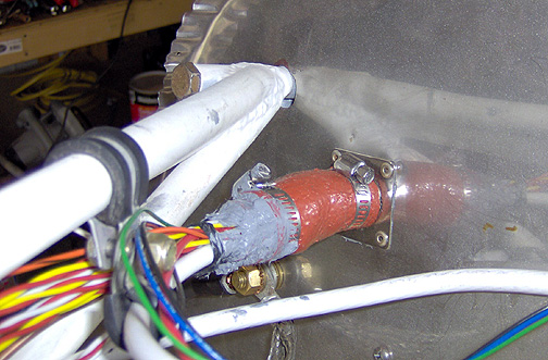
As you can see, there is a piece of firesleeve on the outside held in place
with some hose clamps. What you can't see is that there is another piece
of firesleeve that has been slit down the middle lengthwise and then slipped
inside the outer piece, creating a tight fit for the wires. Finally,
the end is sealed with fire sealant as shown.
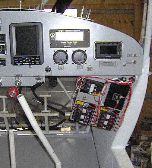
As previously mentioned , the system I'm using will use fuse blocks as the
main electrical buses. I wanted to have good access to the fuses and not
have to crawl under the panel and stand on my head to get to them.
Therefore, I made a provision to have it on the passenger side panel
near their leg. It hinges out for easy access but tucks out of the
way when not needed. Here it is in the open position:
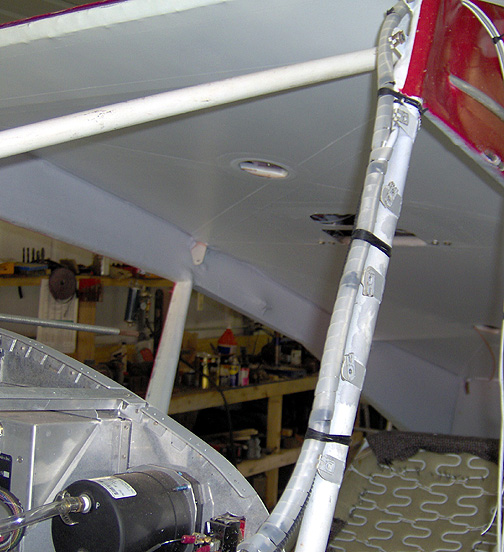
Several wires run out to the wingtips and some run back in the fuselage.
These wires are routed up the forward windshield posts along with the
fuel lines. The general rule is to never run electrical wires with
fuel lines. However, when it can't be avoided, there must be a physical
separation between the two. On mine, the fuel line is covered with
a corrugated plastic sheath as shown here:
The plastic sheath is a split piece of plastic conduit designed for wires.
As an added protection and to neaten things up even more, the wires were
wrapped with a spiral wrap as shown here:
Well that's about it for the electrics for now. All of the wiring under the panel has been completed. The wires that run out to the wingtips are wound up neatly and are hanging off of the wing mounts for now. They will be pulled out to the wingtips after the wings are installed for the final time.
When completed, I was able to test all of the systems. The radio and intercom was powered up and all of the headset jacks were checked for proper functioning. Mickey took a handheld radio and walked off quite a distance to test the radio. The XM satellite radio was powered up and tuned in. The GPS, transponder and EFIS all work great.
Here it is all lit up:

With the instrument panel wiring done, I can move on to the next step of closing up the boot cowl and making the engine cowl. The remainder of the wiring will be completed once the wings are mounted.
Click here to go to the Final Assembly Index page
Click here to go the the Home page