The Bearhawk is a natural for mounting some floats on it and landing on some
lakes. So far, as of this date (April 2010) there are only a couple
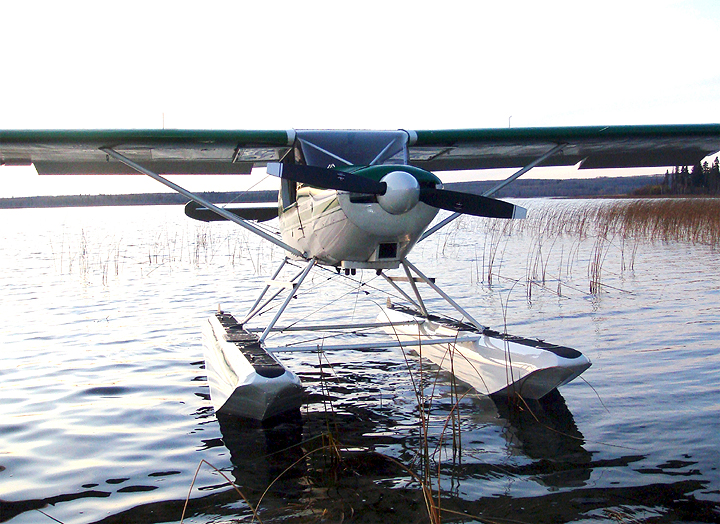
of Bearhawks with floats. One of them is Al Robinson's Lycoming O-360
powered Bearhawk in Alberta, Canada pictured here:
Here are Al's comments on the Bearhawk Float plane - taken from the Oct -
Nov - Dec 2008 BearTracks newsletter:
Al Robinson - Cold Lake, Alberta
When I bought Tom Yeoman’s BH in April, I was well aware of the performance of these aircraft and was convinced that N416TY would make an excellent floatplane. By July I had collected enough money to prompt Claire Sceli of Clamar Floats to begin the fabrication of a set of 2500 straights. These floats meet the float capacity requirements for a gross weight of 2700 lbs. (2500 lbs. per float exceeds the 180% of gross weight float capacity required). By mid October I hauled my newly constructed floats to a father and son team living in Marwayne, Alberta. Charlie and Eddie Seville have scratch-built ten Bushmasters and have decades of experience installing floats.
Float Installation:
Clamar floats are composite—no metal fatigue, no rivets, no water to
pump out, hardly any maintenance. But these floats need to be painted. It
took, about 4 coats of primer—with heavy sanding between coats—to
get rid of the porous surface.
We did a new weight and balance on the aircraft, then removed the gear and slid the assembled floats (spreader bars and boxing wires installed) under the hanging aircraft. Using a plumb bob, we aligned the floats’ c. of g. with the centre of the aircraft c. of g. envelope (see the procedure on www.clamarfloats.com). With the floats centered and level, we pulled down the tail until we had a 3.5 degree positive angle of attack on the bottom of the wing with respect to the deck of the floats. We measured from the front fuselage gear attach bolt hole to the front float attach bolt hole on both sides and took the average. We allowed for a ¾ inch radius around the drilled holes and cut the forward strut lengths accordingly. We cut, drilled, trimmed, and attached the forward struts. The same procedure was followed for the diagonals.
Then we needed to weld on the rear attach fittings at Station E. Eddie wanted to leave this until we could see the angle of the rear strut. Once this angle was established, we cut open the fabric surrounding the welded cluster at Station E—at least an inch beyond the fitting dimension. Pieces of aluminum were duct taped to the perimeter of the weld area to act as a heat sink for the welding. As I stood watch at the cabin door with a fire extinguisher, Eddie welded the Clamar fittings onto the frame. By the way, the 90 degree bends at the corners of the Clamar fittings had to be split and slightly bent in order to get them to contact the longeron. We were then able to measure and cut the rear struts.
The flying wires attach to lugs at the floats and to eyebolts at the fuselage, so these require no additional weldments. They do, however, require extensions in the form of 4130 straps. The strut material came in uncut lengths, so one decision that had to be made was the distance between the aircraft and the floats. We decided to use as much of the strut material as possible and get the aircraft as high over the floats as we could. This for two reasons: it would put the 82 inch McCauley prop (the bigger the disc the greater the thrust on a float plane) as high out of the bow splash of the floats as possible; and the greater length would also provide the aircraft with more leverage on the floats when rotating on take-off. Clamar floats, being of composite construction, are not equipped with splash rails. Common to aluminum floats, they deflect water coming off the bow of the float. To offset this, the Clamar float has a slightly flatter bottom than a typical aluminum float, which tends to deflect the water in a flatter trajectory, thus saving the prop. Rigging the water rudders was straightforward.
We had to make do with 6 pulleys instead of eight, so our configuration was not quite as suggested on the Clamar website. The cabling comes pre-cut from Clamar and is designed to be simply an assemble job, but the lengths did not conform to our requirements (the greater distance between fuselage and floats?). The rudder pick-up cable needs to be routed through the floor, through a 90 degree stainless steel tube that leads the cable along the belly to the rudder pick-up cables. This cable is located on the pilot side of the flap handle and is anchored to a hook on the instrument panel. The 90 degree bend has to be located on the belly panel that contains the gear oleo holes. The stainless steel fitting needs to be installed just where the left hole is, so I’ll have to build a new panel without oleo holes. This replacement panel will also close off the gap normally covered by the gear fairings along the lower longerons. The aluminum steps are located higher than normal on the struts to enable me to lean into the cabin to make loading and unloading easier.
Flying:
A float plane is half plane, half boat, half pick-up truck. Flying anywhere
in central and northern Alberta usually involves a fully loaded airplane.
This means that C of G is always a concern. Charlie says that on wheels I
would have difficulty fully utilizing my rear baggage compartment. On floats,
the BH presents a different story. The floats provide a more forward C of
G for the aircraft; moreover, the float compartments are just forward of
the float C of G. The weightiest item of the load will be the extra fuel.
Placing this fuel just forward of the C of G would provide all kinds of
flexibility in loading the cabin. Each compartment could take as many as
4 five U.S. gallon jugs of fuel. That’s approximately 120 pounds per
compartment. Probably too much. In the spring I will try two in each compartment
and see how they fly. If I can get away with 3 jugs each, it’ll be great.
The problem—according to my experienced float-flying buddies—is
the pendulum effect created by floats hanging beneath a flying aircraft.
I’m sure that you are very aware of what happens to the stall speed
of an aircraft in a steep turn. Imagine what an additional 200 pounds of
floats plus 90 pounds of fuel, plus another 90 pounds of fuel—all of
this approximately 3 feet below the aircraft--would have on the flying platform.
A loaded floatplane requires a healthy amount of respect and perception.
Apparently some floats equipped with compartments are limited to 50 pounds
per compartment and have a warning about conducting steep turns.
So far I have only 2.5 hours flying time on these floats, so obviously there is a lot to learn. A 45 minute crosscountry, a dozen or so stalls—power on/off, flaps on/off, and as many landings and take-offs as I could fit in. Here is what I know so far. My cruise at 60-65% power is 115 mph indicated—5mph slower than on my 8.50 tires. The aircraft has a slightly heavier feel to it, with slightly more control inputs on the rudders—this is not a trim or rigging issue, just my adjusting to the inertia of the floats. Power-off stalls are occurring at 45 mph IAS. Two notches of flap at about 43 mph IAS. Power-on is 40 IAS. Power on and two notches of flap is slower than 40 IAS. There is no change in the crisp aileron control approaching stall that I have become accustomed to in the BH. The only change of note is the extra rudder input. During installation, Charlie and Eddie felt that the vertical stab on the BH was large enough to preclude installing a ventral fin. Ventral fins, according to Charlie, do three things: they counter-act the momentum created by floats in a spin—NEVER spin an aircraft on floats; and they help control torque on a take-off run; unfortunately, they also weathercock the aircraft, making it more difficult to turn a taxiing floatplane out of wind. Turns are slower to initiate on floats and require the usual lead with rudder, followed by a bit of opposite rudder. My approaches have been with 3 notches of flap at 65 IAS in stable wind conditions. Add 10 mph for gusty winds. The BH with its high-lift wing likes to hang out for a while on flare; to complement this, floats require flat, slow flares. So far I’ve been keeping the BH at a manageable 65 IAS, which makes for an efficient, predictable landing. I have yet to try a landing with 50 degrees of flap. A glassy water landing requires two notches of flap for a safe nose-up attitude, and a controllable 100-200 ft/min. descent rate. This will be a spring ’09 training objective.
The Boat:
Claire’s water rudders are very efficient. I experienced no problem
turning out of a 10 knot wind. Wave action on the bows of the floats tends
to drive the splash across as opposed to upwards, thus keeping clear of the
prop. The only caution I experienced was in taxiing downwind when the bows
tended to be lower in the water. I had to be sure and keep the stick back
all the way. Getting on the step is quick and easy. I am still experimenting
with technique here. Once on the step the BH does its usual thing and claws
for altitude. Although I’m still getting used to quickly finding the
“sweet spot,” the BH’s best take-off time so far is 10 seconds
(with 330 lbs. of fuel)—not bad! The Lycoming 0-360 with an 82 inch
constant speed prop seems to be an ideal configuration for this plane on
floats: power and efficiency from the engine, thrust from a huge prop disc,
and 1150 pounds of useful load (2700 – 1547 pounds). The BH, given its
incredible flying characteristics, gives basically the same performance as
a Cessna 180 on floats!
Al Robinson - Cold Lake, Alberta
Click here to go to the Home page