March 14, 2005
The vertical stabilizer is built in place on the tailpost. To build it correctly, the rudder must be installed on the tailpost or at least clamped in place. This is because the vertical stabilizer top must be angled to match the front top edge of the rudder. The rudder was installed on the tailpost using the same techniques as was used on mounting the Elevators to the Horizontal Stabilizer.
Now, with rudder in place we can start building the vertical stabilizer.
It starts with the 5/8" front tube and the top T25 piece. The
front tube must be curved slightly to make a nice blend with the rudder.
The top T-25 rib must be spaced 9/16" from the top of the rudder and
spaced evenly. The T-25 rib was clamped to the rudder with a couple
of wood blocks as shown below:
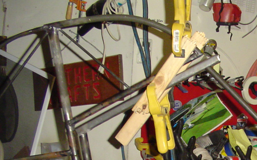
This maintains the proper gap and alignment while you fit the forward tube
to the vertical stabilizer. Here is the forward tube being fitted in
place:
You can see that we have a nice, even curve that flows nicely into the top of the rudder. Alignment of the forward tube is important. As previously discussed, if you are using a standard Lycoming or Continental engine, the vertical stabilizer is canted to the left 3/4" off the centerline of the fuselage. The best way to check for proper alignment is to clamp the bottom of the vertical stabilizer forward tube in position at the fuselage. Then standing at the front of the fuselage site down the tail and see if the vertical stabilizer tube is aligned with the tailpost full length. Move the rudder and top T-25 tube of the vertical stabilizer until the vertical stab. tube aligns with the tailpost as viewed from the front of the fuselage (slight left of the centerline) Proper alignment will cause a slight right rudder position. Once its properly aligned, tack weld the vert. stab tube to the fuselage, and the T25 top rib to the tailpost and vertical stabilizer front tube.
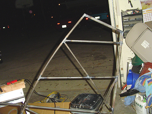
The remaining ribs can now be fitted and don't forget to put the T-5 tube
in place as shown in the plans and in the picture below. Weld all the
joints and post heat the tailpost behind all welds to keep it straight.:
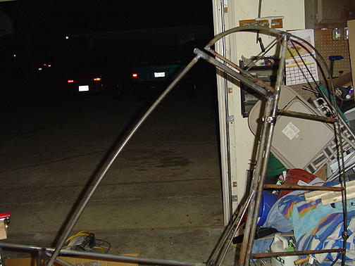
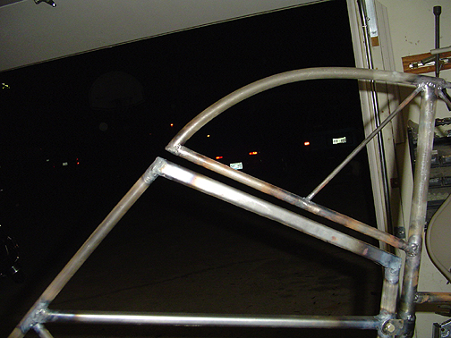
Here is a picture with rudder bolted in place. This shows the fit of
the front tube to rudder and the even gap of the rudder to vertical stabilizer
interface:
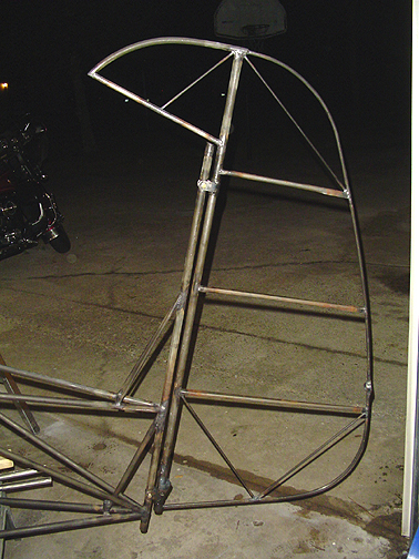
Here is a picture of the finished product with rudder attached:
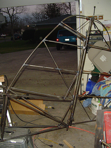
Vertical Stabilizer
Completed: March 16, 2005
Total Time: 8 Hours