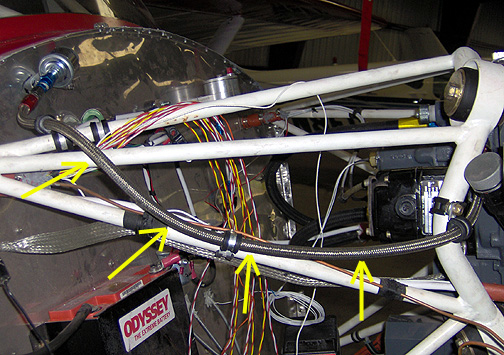
The oil cooler hoses were made with Aeroquip 303-10 hose (1/2" I.D.) and Aeroquip 491-10D end fittings. Also note that firesleeve was installed over the hoses where they run under the cylinders.
Started April 1, 2008
Different engines will have different locations for the various plumbing and wiring hook-ups. The following will show the hook-ups for the Lycoming O-360.
I started with hooking up everything related the oil system. This includes
the hoses connecting the oil cooler to the engine:
The oil cooler hoses were made with Aeroquip 303-10 hose (1/2" I.D.)
and Aeroquip 491-10D end fittings. Also note that firesleeve
was installed over the hoses where they run under the cylinders.
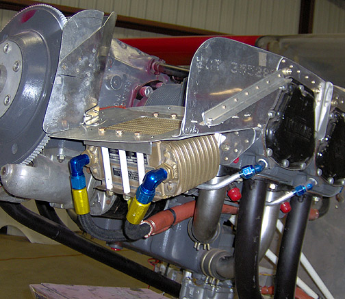
The oil cooler hoses were made to the correct length and attached to engine
as shown below:
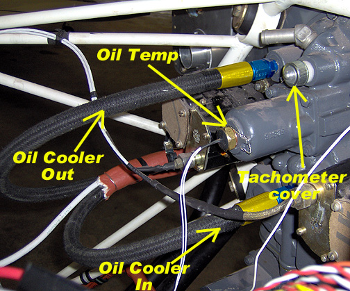
Note that I used straight fittings coming out of the engine. Also shown
in the above picture is a couple of more details. If you are using
an electronic tachometer, the tach cable hookup on the engine must receive
a cover (Avery's Tools P/N 6346).
Also shown above is the oil temperature sender for the Grand Rapids
Technologies EIS system).
Next on the list is the Oil Pressure sender. This item should
not be mounted directly to the engine as it could eventually fatigue
and break due to vibration. Instead, it is recommended that you mount
it to the firewall or other suitable structure and run an oil line to it.
Here is the oil pressure sensor mounted to the firewall:
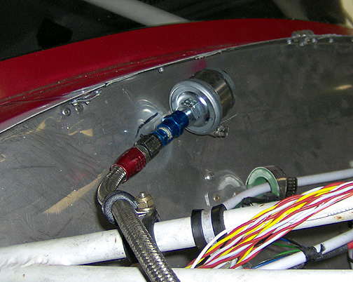
The sensor shown above is simply mounted to the firewall using a hose clamp
and a strap of aluminum, pop riveted (Stainless) to the firewall. You
can see how the mount works by looking at the amp shunt mounted directly
below the sensor. Its simply a strip of aluminum, riveted on to the firewall,
trapping the hose clamp in between.
The hookup on the engine for the oil pressure, is a 1/8" port right next
to the upper right engine mount. You can't see it in this picture but
I used an AN832-4 (45 degree) fitting in the engine port. Here is the hose
running from the oil pressure port on the engine to the oil pressure sender
on the firewall:
The hose is Aeroquip 601-4 with Aeroquip 816-4 end fittings. I had no
particular reason for using the 601 hose other than I had some left over
from a previous project so I used it. You could use Aeroquip 303 hose which
is less expensive.
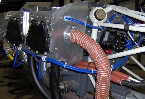
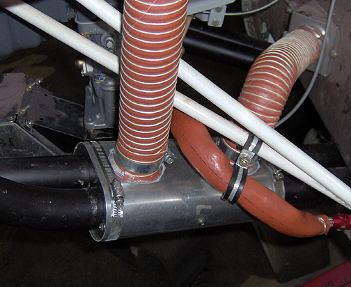
The cabin heat muff and scat ducting was installed as shown below:
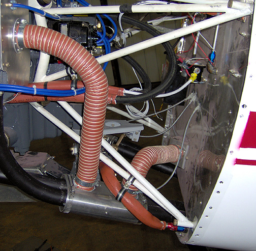
Here is a closer picture of the
Robbins heat muff. As
you can see it wraps around both exhaust pipes:
I paid particular attention to making sure that none of the exhaust system
welds fall within the heat muff (risk of carbon monoxide poisoning). The
firesleeved hose seen in the picture above is the fuel hose running from
the firewall bulkhead to the carburetor.
Here is the carburetor heat muff (also from
Robbins Heat Muffs)
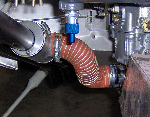
When I started installing the above heat muff, I discovered that it didn't
need an air inlet. The side between the exhaust pipes is open. So
it turns out that I didn't need to install the ducting flange on the right
rear baffle after all, so it was removed and a patch was made to cover the
2" hole.
Also note in the above picture that I have installed a quick drain (Aircraft Spruce P/N P5000) for the oil sump. When changing the oil, I can simply attach a hose and run it out the rear cowl opening, draining it into a bucket.
The spark plug wiring harness was installed and the wires were routed as
shown below: