The top part sits to within 1/16" of the top of the pulley, so the 1/8" cable cannot slip off. The long leg with a tab will be used to prevent the guard from rotating.
January 23, 2008
As previously mentioned, all control system pulleys require some sort of cable retainer to prevent the cables from slipping off of the pulley, should it become slack. There is probably no control system on the Bearhawk that is more susceptible to slack in the cable than the Flap system. This is because it is a one way system (i.e,. the cable only pulls the flaps down, but springs pull the flaps back up). When you taxi in a strong enough tail wind, the wind can actually overcome the strength of the springs and make your flaps go down, thereby putting slack in the cables. Without proper pulley retainers, these cables can fall right off the pulley.
The cable retainers have a couple of requirements:
1. They must come close enough to the pulley to prevent the cable from coming
off, without actually touching the pulley.
2. They should be secured to the surrounding structure so they cannot rotate.
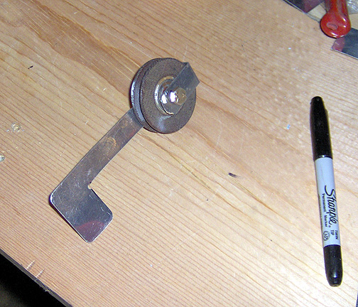
Here is my rendition of the cable retainer for the flap pulleys:
The top part sits to within 1/16" of the top of the pulley, so the 1/8"
cable cannot slip off. The long leg with a tab will be used to prevent
the guard from rotating.
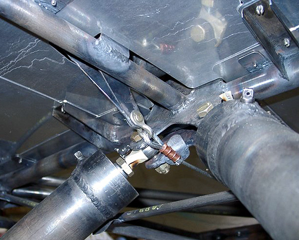
Here is the pulley and its cable retainer installed in the fuselage:
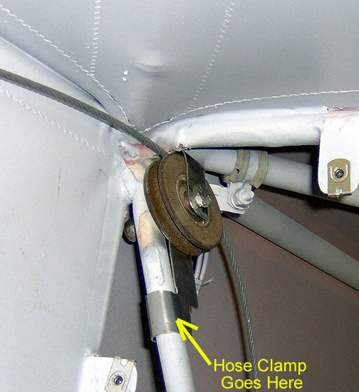
As you can see, the little tab has been wrapped around the "V" tube at
the baggage bulkhead location. I will install a hose clamp there later
to fully secure it to the tube.
Likewise the pulleys up near the rear wing attachment on the fuselage need
cable retainers.
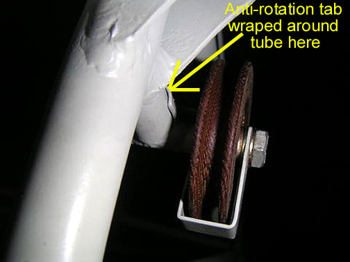
Photo courtesy of Bill O'Sullivan
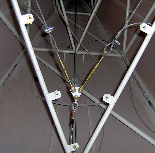
The next item that must be fabricated before we can finish off our flap system
cables, is the triangle cable junction piece, where the one cable splits
into two cables, just aft of the baggage bulkhead. The newer plans
call for a piece of .125" thick 4130N steel plate for this triangle.
This piece and the connecting bolts, will endure some fairly heavy loads
so .125" thick is required here. Here is the set-up with the turnbuckles
installed:
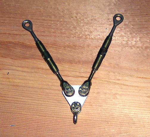
The cable shackle at the bottom will connect to the cable coming from
the flap handle in the cabin. The two turnbuckles will attach to the
cables coming from each flap control horn.
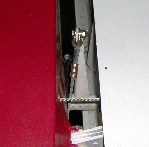
The first cable was attached at the bottom of the flap handle with a cable
shackle. This cable rubs slightly against the shock strut mount only when
in the fully retracted position. It clears it as soon as the handle is moved
to deploy the flaps. One builder, Pat Fagan, welded on a steel "skid
plate" to account for this:
Fagan's #232 Bearhawk - courtesy of
Russ Erb's CD
The cable comes off the flap handle and is threaded through to the two gang
pulleys on the fuselage bottom. This cable is threaded through the
furthest pulley on the starboard side (passenger side) of the fuselage.
Next a cable was attached to each flap drive horn on the wing root:
Note that the cable is oriented with the cut side of the cable facing downward.
This helps prevent interference with the aft wing spar attachment piece.
These cables were then threaded through the flap
system pulleys and fairleads to meet at the cable junction triangle:
Notice in the picture above that the bottom cable has been installed
with a regular crimped Nicopress sleeve. However, the cables running
up to each flap have only been temporarily clamped with hardware store cable
clamps, for now. This will allow us to adjust the length of the cable
before making the final connection.
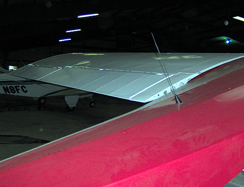
Now the flaps are mounted on each wing and the push rod for each flap is
attached between the flap drive and the flap hinge. The flap retraction
springs were also installed at this time The rod end bearing in
the flap pushrod was then adjusted until the flaps were in the full "up"
position, with the pushrod "T" resting against the rubber stop, and the flaps
aligned with the wing root trailing edge:
Click here to go to Rigging the Flaps page 2