Wingtips page 2
Next I will be installing the combination LED Nav Lights/ Strobes/ Landing
lights in the wingtips and fitting a clear plexiglass lens. The electronic
parts of this lighting system are available from
Creativair. Those are the electrical
parts, but you will still need to manufacture the wingtip insert, and then
form and fit a clear plexiglass cover for it.
This should be lots of fun and a real challenge. Before we start, let
me show you what we are trying to accomplish here:
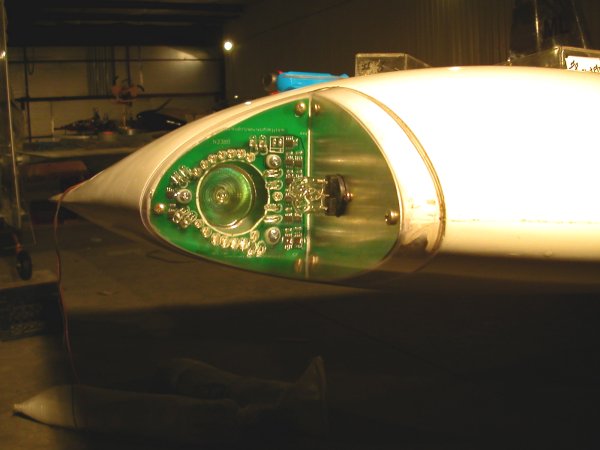
Note: This is not a Bearhawk wingtip but it shows what I'm trying to
accomplish. As you can see, there is an adjustable landing light (75
watt Halogen), surrounded by colored (Red or Green) LED nav lights
on the back wall. A strobe light is installed on the side wall. The
side wall has an unpainted aluminum piece installed for reflectivety. As
you can see, the clear lens sits on a joggled flange which allows it to be
perfectly flush with the outer skin of the wingtip.
Of course the above wingtip setup does not cover the required lighting for
the aft end of the airplane. I have installed a white tail light with
a strobe in the Rudder for that.
OK - here we go:
I purchased the clear lenses, made for the Vans RV-10 wingtip lights. I
was hoping that they would be close enough that with a little heat and forming,
they would fit. The lenses come from Van's
Aircraft as one, canoe shaped piece, that you have to cut in two. Of
course, these did not fit as well as I had hoped. They were quite a
bit larger and a different shape than the Bearhawk wingtip, so we had to
do some shaping.
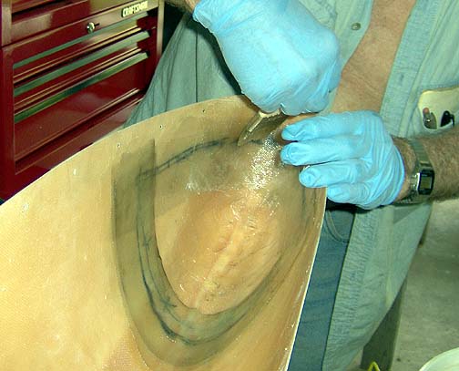
Here was Mickey's idea for shaping the Van's RV10 lenses to the Bearhawk
wingtip (note: the heat gun is not being held as close to the plexiglass
as it looks in the picture):
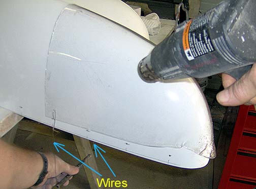
We started by drilling a couple of holes about 1 inch in from the back corner
on each side. Then a piece of safety wire was strung through the holes
and a piece of 1/2" tubing to act as a handle (as shown above). The
lens was placed in position on the wingtip and using the wires and handle,
pressure was applied downward and rearward at about a 45 degree angle, while
the heat gun was used to evenly heat the lens all over. This allowed
the lens to form to the contour and shape of the wingtip to some extent.
As you can see in the above picture we ended up over-heating the front
edge of the lens, causing it to bubble and distort a bit.
Fortunately, that portion of the lens will be cut away in the final
trimming.
If I had it to do again, I would probably use Erbman's method of forming
the wingtip lenses. To see that, you will need to get your hands on
a copy of Russ Erb's
Bearhawk Reference CD .
With the lenses formed to the wingtip, we can go ahead and figure out the
cutout. The goal is to have the lens sit against a 5/8" flange that
is joggled in just enough to allow the lens to be perfectly flush with the
wingtip when it's installed. The following will describe how we made
the joggled flange.
As previously mentioned, I will be using the LED Nav light setup available
from Creativair. To determine
the depth of the cutout needed, I first measured the height needed for the
LED circuit board that comes with the LED nav light kit. I then added 5/8"
for the joggled flange that the lens will be attached to.
Here is the cut line, rough drawn on the wingtip:
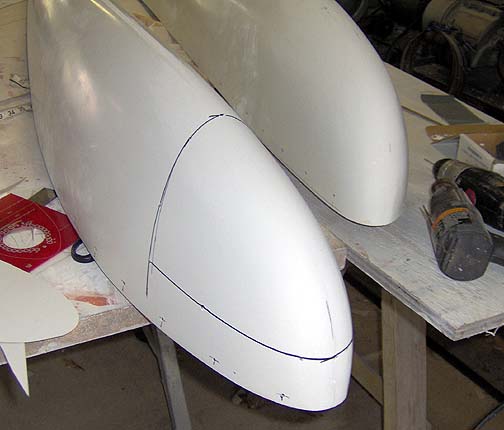
Per the Creativair instructions, the aft end of the cutout should be tilted
back 10 degrees from perpendicular to the wing's edge, to get the proper
azimuth coverage of the position light.
The joggle in the flange should be just deep enough to allow the lens to
sit flush with the wingtip skin. I found that the lens was about the same
thickness as the wingtip skin, so the actual piece that will be cutout was
used as a template to make the flange. Here's how:
First, cut the wingtip on the line:
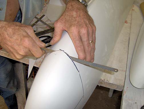
As you can see, we started out using a hacksaw blade. Don't use a hacksaw
blade as it very hard to keep proper alignment on both sides of the wing
tip at once. We later changed to a dremel tool with a cutoff wheel installed,
which was much more controllable. The piece was cut out, but not completely
A couple of 1/4" places in the corners and at the top of each curve
were left intact to hold the cutout piece in place temporarily for the next
part of the operation, the forming of the flange.
One thing nice about fiberglass is that it doesn't stick too well to clear
packing tape. So you can simply put some packing tape where you don't
want it to stick and leave it bare where you do want it to stick. In our
case, we are going to lay up several layers of fiberglass inside the wingtip
at the cut line. We do not want the fiberglass to stick to this
cutout piece, but we do want it to stick to the surrounding area.
The wingtip was flipped over so we could access the inside. On the inside
of the wingtip, the cutout piece was carefully covered with 2" clear packing
tape being careful to not make any wrinkles in the tape near the edges, where
the flange will be. The tape was only placed on the cutout piece and
not on the surrounding area outside of the cut.
The 2" area outside of the cutout piece, where we want the fiberglass to
stick, was thoroughly sanded with 80 grit sandpaper and then completely
cleaned using MEK solvent.
With these preparations completed, some 3" wide strips of fiberglass, cut
on a 45 degree bias to the grain, were adhered to the cutout area with some
Polyester resin (note: Epoxy resin would probably be a better choice, but
I am deathly allergic to the stuff. The Polyester is acceptable in this case
since the wingtips were made with polyester resin as well).
We left 2" of the cloth overlapping the outer perimeter of the cutout and
1" overlapping the inner perimeter (taped part) of cutout area:
Be careful to stay away from the area where the wingtip will attach to the
wing or you will build it up too much.
We layered 7 or 8 strips of fiberglass cloth to build up the thickness
of flange area, filling the weave with Polyester resin and smoothing it out,
to eliminate any bubbles.
This was allowed to cure for a couple of days. Once fully cured, the
wingtip cutout can be removed. First, the dremel tool was used to finish
the cut, then the cutout area was removed. As previously stated, the
fiberglass didn't stick to the tape, so the cutout area was removed easily.
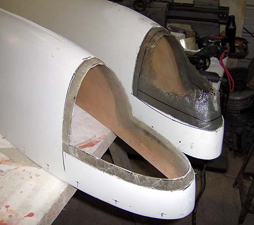
The flange was final trimmed to 5/8" wide, using a dremel tool with cutoff
wheel installed. In the above picture, the closest wingtip's flange
has been trimmed and the other one has not been trimmed yet. This is what
it looks like right after removing the cutout area.
One more check of the fit of the lenses:
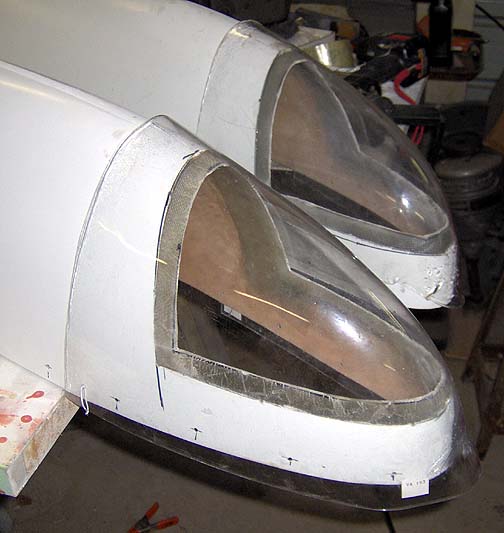
Looks good so far. I'll hold off on final trimming the lenses until
the back and side walls are made.
Click here to go to Wingtips page 3