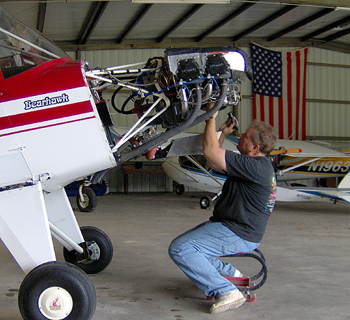
Now with everything opened up, we can start our inspection. I started by using a spray-on degreaser to thoroughly clean the engine and then rinsed it off with a high pressure nozzle on the water hose.
I used a high intensity flashlight, inspection mirror and, in my case, some
reading glasses for the inspection. Starting at the front, I systematically
worked my way back to the tail, slowly and thoroughly looking at every part,
bolt/nut, and in every nook and cranny. This part took almost an entire
day:
Sometimes I would just lay under the airplane on a creeper, or inside the cabin laying on my belly, under the instrument panel on my back. I really spent a lot of time just looking at things, in fact at everything, trying to find a crack starting at the edge of a metal panel, a loose nut or clamp, fluid leaking, a wire or tube rubbing against something and wearing, a frayed cable, wear on the edge of a pulley, anything that just doesn't look right. This part takes time, and requires patience to do it right.
As I went along inspecting, a list was created noting each item that I came across that needed some attention, creating a fix-it list.
Now I'll go back and correct all deficiencies found. I'm also taking this opportunity to install a few items that I've been wanting to install (An Oil/Air separator, Fire Extinguisher, a bit of insulation, and some rubber seals for the windows and doors).
Firewall Forward Items
Compression Test
The bottom spark plugs were removed (carefully noting which cylinder each
plug came from) and a compression check was performed on the cylinders. I
borrowed a differential compression tester from a friend at the airport for
this test.
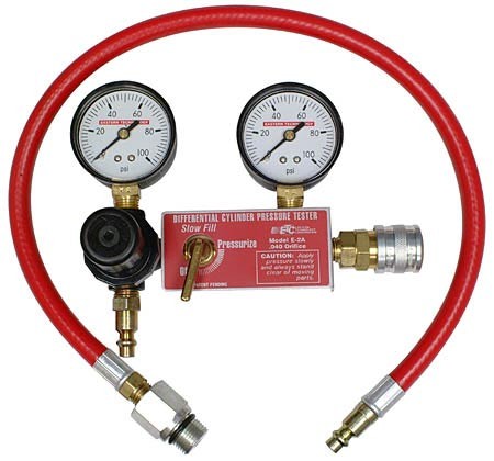
Here is how to perform the compression test:
1. Rotate the prop by hand, in the normal direction of rotation (counterclockwise
as viewed from the front) until one of the cylinders comes up on compression.
You can determine this by placing your thumb over the spark plug hole and
feeling for a pressure buildup.
2. Now, install the adapter (supplied with the compression tester) in the spark plug hole of the cylinder to be tested. Be certain that the air shutoff valve on the tester is off and connect the differential compression tester. CAUTION: Be absolutely certain the shutoff valve is closed and that you have a firm grip on the tip of one blade of the prop before connecting the system to your source of compressed air.
3. You will now have to find top dead center on the cylinder being tested. The easiest way to do this is to adjust the pressure regulator to about 20 psi and open the air shutoff valve. Carefully rotate the prop in the normal direction of rotation against the 20 psi pressure until you feel a "flat spot" or rapid loss of turning resistance. If you go too fast, back up beyond top dead center and try again. It is critical that you reach TDC with the prop turning in the normal direction of rotation, not while backing the prop up since this would unseat the piston rings. The piston rings must be at the bottom of their lands in the piston with the piston at the top of its travel.
4. Now, be certain you have the prop tip securely held. This is a good time to have a second person to help you. The air shutoff valve should be open and the pressure regulator adjusted to show exactly 80 psi on the pressure regulator gauge ' Use caution because if you let the prop move in either direction beyond TDC, it will rapidly begin to rotate and it could beat the tar out of the unfortunate person who should have been holding it securely! Now, gently move the prop tip back and forth, just a tiny amount. Watch the cylinder pressure gauge and take a reading from it at its peak steady pressure. Again, this will be while moving the prop in the normal direction of rotation. Be certain that the regulator pressure gauge is holding precisely 80 psi. You should have a differential pressure reading of between 60 and 78 over 80. Repeat this test as consistently as possible on all cylinders.
You should now have a series of numbers something like this, depending on
the condition of the engine: 76/80, 74/80, 73/80 and 75/80. These numbers,
hopefully, will be fairly close to each other in magnitude. What are the
limits? What constitutes a bad (too low) cylinder? It is generally accepted
that a cylinder reading below 60/80 (on a Lycoming engine) would require
removal from service. There is no rule or law that says this is the case.
In fact, the FAA as well as the two engine manufacturers have no such
requirement.N57EN's engine had the following results (engine tested cold):
Those results look pretty good to me, so I'll move on to the next engine test.
Magneto Timing
Next, the magneto timing was checked. I have a magneto timer with 4 wires.
One goes to the (pos+) terminal of the battery, one to ground (neg
-) of the battery and the other two wires hook to the "P" lead connector
on each magneto. There are two lights on the timer that light up when each
mag's points just start to open indicating the point at which the mag fires.
For my engine, both mags should fire at 25 degrees BTDC of the number one
cylinder. This is marked on the engine flywheel. The left mag was found
to be set to exactly at 25 degrees before top dead center (BTDC), but the
right mag was firing at about 15 degrees BTDC. The right mag was adjusted
until it fired at exactly the same time as the left one (both lights on the
timer light simultaneously).
Cleaning, inspecting and reinstalling the plugs
The top spark plugs were removed (again keeping track of which cylinder each
one came from) and all plugs were cleaned with an air operated spark plug
cleaner and inspected. The gap was checked and the plugs were re-installed.
When reinstalling the spark plugs, they were swapped to different cylinders
and from bottom to top. In other words, the spark plug from the bottom
of cylinder #2 was installed in the top of cylinder #1. The top plug
from cylinder #1 was installed in the bottom of cylinder #2, etc.
Installing Air/Oil Separator
Even now that the engine is fully broken in, I still get a little oil on
the belly of the airplane from the breather line. So, while the cowling is
off, giving me good access to the firewall, I have decided to install
an Air/Oil separator. The one I went with was fairly inexpensive ($55),
and all aluminum (Wick's P/N OIL-BS5/8) making it very lightweight. It is
simply installed in-line on the breather hose and is attached to the
firewall:
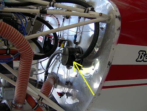
The 5/8" breather hose still curves up as it leaves the engine, then runs
down and attaches to the oil/air separator mounted on the firewall. The air
then passes through the air/oil separator to the outlet hose which runs down
to the bottom of the firewall. The trapped oil runs down a small tube
at the bottom. The idea is to run the oil back into the engine but
I personally don't like that idea, as I would imagine that you also get some
water and other engine gunk in there. So, I simply put a length of clear
hose with a shut-off valve at the end. This hose will be checked during
pre-flight and emptied occasionally.
Cracked Starter
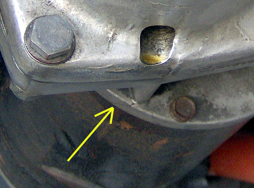
During the engine inspection I found a small crack on the starter housing,
right where the starter motor attaches to the housing:
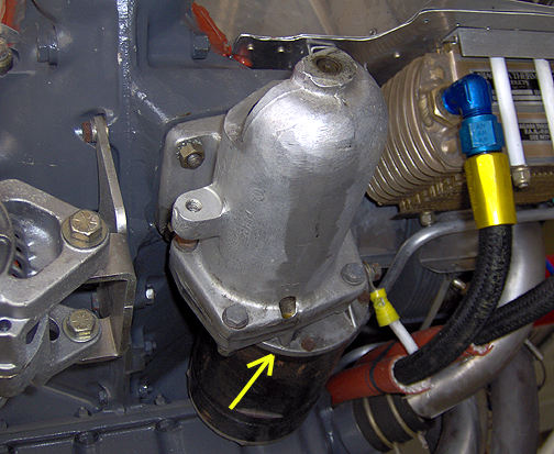
The arrow points to the location of the crack.
Close-up view of the crack. This is a hair-line crack that goes all
the way across the housing:
Arrow points to the crack.
David Weber from the Yahoo Bearhawk group had an extra starter laying around his shop and generously offered it to me in exchange for a Bearhawk ride. What a deal! He wouldn't even let me pay for the shipping. The cracked starter was replaced with the one David sent me and it works great - problem solved. Thanks again David - I owe you a Bearhawk ride.
Scat Tube Rubbing Engine Mount
When I disassembled the cabin heat muff to inspect the underlying exhaust
pipe for cracks, I found that the heat muff had slipped down the pipes a
bit, allowing the scat tube to rub on the engine mount. So far it has
just rubbed the paint off, but needs to be better secured when I re-assemble
it.
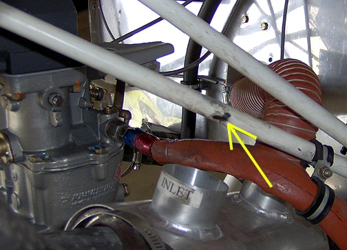
Arrow points to rubbed spot on the engine mount.
To prevent the heat muff from sliding down in the future, I simply put a
weld bead, standing up about 1/4" tall on the exhaust pipe near the back
end of the heat muff. If the heat muff tries to slide down it will
come up against the weld bead and stop right there.
Exhaust Pipe Hitting Bottom Skin of Fuselage/Firewall
Tunnel
When I built the exhaust, I made it just barely clear the bottom of the firewall
tunnel. It looks like I made it a bit too close, as I can see evidence
that it has been making contact with the tunnel area of the boot cowl:
Before: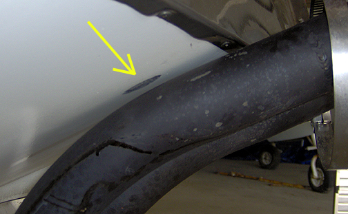
Arrow points to the rub mark where the exhaust pipe has been making
contact.
To create a bit more clearance between the exhaust pipes and the tunnel, I
needed to slightly bend the pipes downward a bit. First, a wood shim was
wedged between the exhaust pipes and the tunnel skin (bottom of firewall)
to apply downward pressure on the pipes. Then, a torch was used to heat a
1" long area around each exhaust pipe, near the first bends (under the
cylinders). This allowed the pipes to "relax" down a bit to give about 1/2"
more clearance:
After: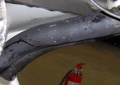
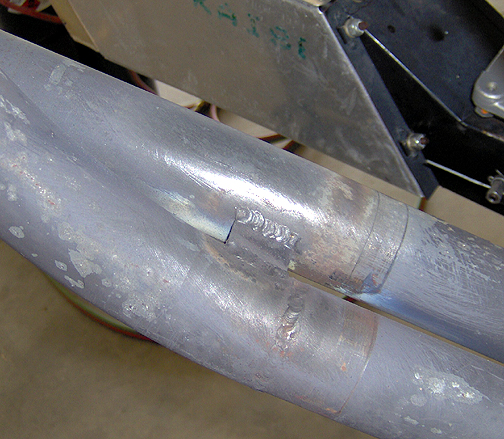
Exhaust Pipe Modification
While at Sun n' Fun, Bob Barrows mentioned that he would like to see the
two exhaust pipes, on each side, connected together to give them more stability
and support. To do this, I used some .060" thick steel plate strips
and welded them between the pipes. These strips were installed on both top
and on the bottom of the exhaust pipes:
Click here to go to Annual Condition Inspection page 3