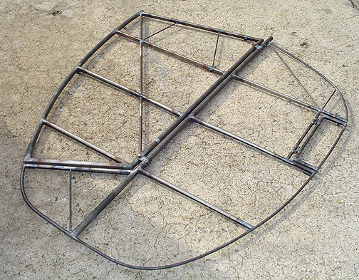
The Elevator was tack welded in the jig, flipped over and tack welded on the backside, then after some tweaking to get it straight again, it was final welded on both sides, straightening as needed to fit the jig.
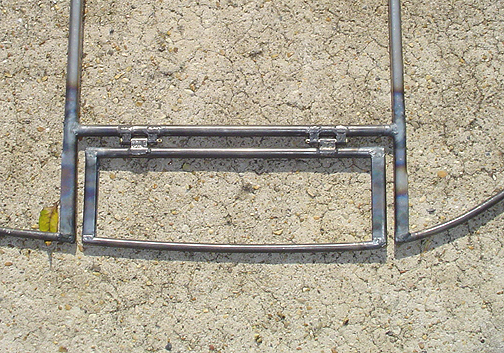
Here is the finished trim tab section:
To check the fit, the elevator was bolted to the horizontal stabilizer and placed out in the driveway. Since the hinges and grease fitting nuts hold it a little high off the ground, some shimming was done on the aft and forward ends.
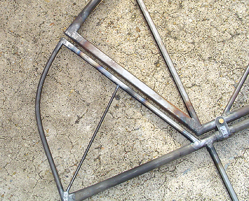
Here is the counter-weight area of the elevator (forward of the hinge line):
I am very happy with fit up of the elevator to the stabilizer. It was worthwhile to begin by drawing the stabilizer outline on the table then jigging the elevator parts up to fit the stabilizer. As you can see, the match up is perfect and even full length.
Here is the left elevator bolted to the horizontal stabilizer:
The right elevator was built in the same jig using all the same techniques.. The only difference was the hinges were faced so the grease fittings were facing up when in the jig. That way, when the elevator is flipped over to be fitted to the right side of the plane, the grease fittings will be on the bottom side.
The elevator counter-weights were made next. There are a couple of
ways to do this. I used the pour in place method. I started by
making a welding a short T-25 rib in the counterweight area as shown
below:
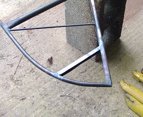
A piece of aluminum plate was clamped to the bottom with some ribbon caulk
as a sealer. The molten lead was then poured
in:
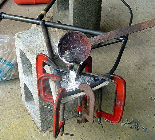
Doing it this way, the lead is contained in the T-25 ribs and can't go anywhere.
It will later be drilled to balance as it is a bit heavy at this time.
Now its on to the Rudder.
Elevators and Trim Tabs
Completed: November 26, 2004
Total build time: 40 hours
Click here to go back to Elevators page 2