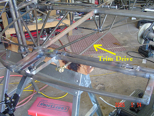
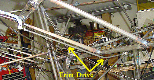
At the other end of the elevator trim torque tube is a simple drive arm:
Also pointed out is the 5/8" tube that is welded in place to keep the torque tube assembly from moving side-to-side. Again, make sure that the trim horn is off-set 3/4" from the fuselage centerline to allow clearance for the upper elevator cable. Once everything is properly positioned, the 5/8" tube is slid in place and welded to the torque tube. The drive arm was then slid on the torque tube and aligned vertically, to be at the same angle as the trim horn.
Next, the trim tab itself must receive a piece for the trim drive tube and
rod end to connect to. Here is one of the pieces that get welded to
the elevator trim tab:
Here it is welded to the trim tab:
The last bit of business is to make the drive tube that connects the trim drive arm to the trim tab itself. There was an Engineering Change in Jan 2004 for this tube to be changed from 1/4" to 5/16"x.028" tube.
The drive tube is fitted on each end with a rod end bearing. The ends of the tube need to have a 10-32 nut welded on to allow the male rod end bearing to screw into. I used Aurora MM-3 rod end bearings for this application.
The drive tube must be bent to allow full "up" elevator travel.
Here is the trim tab drive with the elevator and trim in the neutral
position:
Here it is with the elevator in the full "up" position.:
Elevator Trim Tab Drive System
Completed: May 14, 2005
Total Time: 20 hours
Click here to go back to Elevator Trim Linkage page 1
Click here to go to the Tail Index page
Click here to go to the Home Page