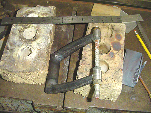
The bushings at the end of each fork must be spaced the correct amount to allow the tailwheel to fit. The tailwheel was assembled with the bearings and spacers and then a measurement was taken to determine the spacing of the fork bushings. Using this measurement a piece of all thread was used to hold the correct spacing and alignment for welding:
The bushings were made on the lathe from 3/4" steel rod.
It is important to make sure there is no twist in the fork assembly. Check to make sure the bushings are parallel to the top cross tube of the fork assembly and that the bushings are equal distance from the top cross piece. They should also be centered side to side so the tail wheel will be centered when bolted in place.
With everything double and triple checked, the bushings were welded in place. With the bushings welded in place, we can test fit the tailwheel and take a couple of laps around the garage:>) This where the boo-boo was discovered. Click here to see that and then return to this page using the "back" button on your browser.
Fast forward another all day session and I have made a new tailwheel fork, this time the correct length.
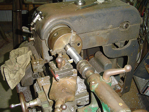
The kingpin was made on the lathe using some solid 4130 steel rod. This
stuff is a little harder than the 1018 steel used to make the body, so the
machining was a little slower but went well anyway:
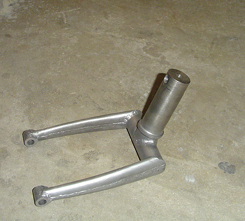
The king pin was notched at the bottom end to perfectly fit the cross tube of the fork. Here is the kingpin welded to the fork at the correct angle:
Now, one more test fit of the wheel and tire (just to be sure):
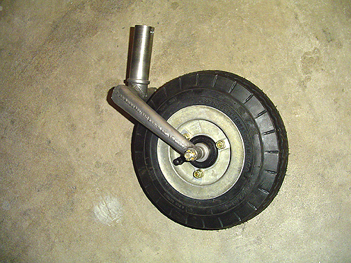
Fits perfect this time.
The tailwheel steering arm has a spring loaded pin built into it. Here is the steering arm showing the locking pin assembly:
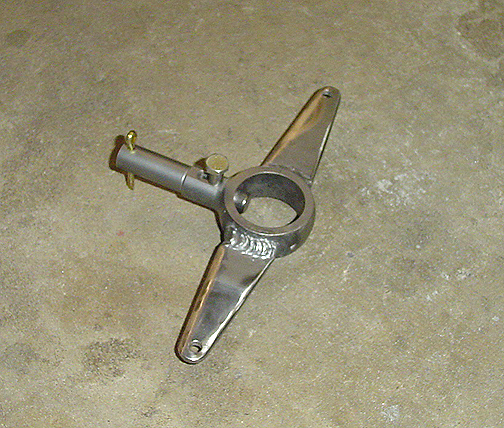
The bolt that you see sticking up rides against the .125 cam that is welded to the top of the main body. There is a spring inside held in by the cotter pin and pushes the locking pin forward. The pin locks into a hole in the king pin for positive steering with the rudder. When the tailwheel reaches a certain angle of deflection in either direction, the cam, on top of the main body of the tailwheel assembly, forces the bolt and pin aft until the pin disengages from the kingpin, thus allowing a full swivel tailwheel. When you straighten the wheel up again, the pin re-engages in the hole and the tailwheel is locked again for positive rudder steering.
Here is the steering arm disassembled so you can see the internal components. Also shown is the top cap that bolts to the king pin assembly to hold it all together:
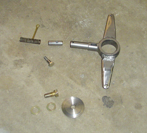
The bolt that screws into the locking pin has a little bushing on it, that rides on the cam to prevent wear on either part.
Finally, here is a picture of the tailwheel assembled and ready to be test driven around the neighborhood:
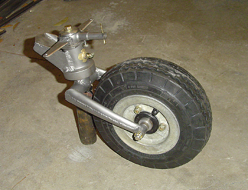
note: The dark piece of tube is not part of the tailwheel assembly.
Its just being used to prop it up for the photo-op.
Since all of the parts have been bead blasted, I'll now clean them up and put on a couple of coats of Epoxy primer to prevent corrosion. I plan on eventually painting the tailwheel assembly and springs black.
Click here to go to Tailwheel page 4
Click here to back to Tailwheel page 2
Click here to go to the Fuselage Index page
Click here to go to the Home page