The forward horizontal stab. mounts require a couple of plates be made that fit between the vertical tube at station "J/H" and the diagonal tube that runs from station "J" to the tailpost.
The mounting brackets should be installed at a -4 degree angle to the fuselage centerline (level in flight).
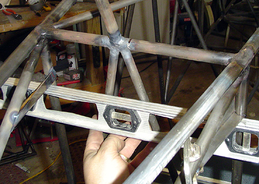
After the first bracket was tack welded in place, the second one was fitted
and made to be level with the first. Using the level as shown below also
allows you to make sure the bottoms of the brackets are flat and inline with
each other. The other mounting bracket was also set at -4 degrees
incidencee:
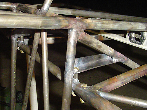
Once both brackets were properly aligned, they were welded in place.
The cross mounting tube was made next. To assure proper alignment of the holes in the mounting tube and mounting brackets, both horizontal stabilizers were clamped in place with the mounting tube between them. The center of the mounting tube was marked before assembly to assure that it was properly centered between the two Horizontal stabs. Again, using the angle finder tool, the horizontal stabilizers were clamped in place with a -4 degree angle of incidence. Using the mounting brackets as a guide, the hole locations were marked on the cross tube so that the holes would land centered on the mounting brackets. The holes were not drilled in the brackets yet, that will be done later.
The cross tube was then removed and the holes drilled at the proper locations. To assure the holes were parallel with each other, the tube was clamped in a drill press clamp and not moved in the clamp until both holes had been drilled with the drill press. The holes were opened up to 3/8" for the 3/8 x .058 bushings as per the plans. The bushings were left extra long for welding then cut and filed to the proper length as shown in the full size drawing. They were then cleaned out with a 1/4" drill bit.
Here is the completed front mount for the horizontal stabilizer:
If needed, the length of the spacer bushings can be adjusted to achieve the
-4 degrees. I found that using the lengths and measurements shown
in the plans worked out just right and my stabilizers were at exactly -4
degrees of incidence.
Here is the empennage at this point:
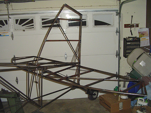
Hey - this thing's starting to resemble an airplane!
Next I'll fit the Flying Wires and Support Strut on the horizontal stabilizer.
Click here to go to Mounting the Horizontal Stabilizers page 3